With so many gearbox technologies and styles to choose from, selecting the right product for a given speed reduction application might seem a daunting task. Dave Brown of Brevini UK offers this design guidance.
The gear is one of the oldest power transmission technologies known to man, with Aristotle describing a simple gear arrangement as early as 330BC, and Archimedes using gears in various constructions in the third century BC. The fundamental purpose of a gear drive has not changed since those early days: to transmit uniform motion between two shafts at a constant ratio.
Many factors impact on gearbox selection in a given application. Consideration must be given to the required ratio, speed, power and torque – not just the continuous torque, but also the repetitive peak torque, acceleration torque and braking torque. But there are many factors which will impact on the most appropriate gearbox selection, including shaft alignment, duty cycle, backlash, efficiency, mounting arrangements, size, weight, noise, smoothness of transmission, operating lifespan and maintenance requirements.
So let’s look at the various common gearbox arrangements, and examine their features and benefits, advantages and disadvantages.
The simplest type of gear is the spur or straight cut gear, comprising a cylinder or disk with teeth projecting radially aligned parallel to the axis of rotation. These gears can be meshed together correctly only if they are fitted to parallel axes. They can handle high gear ratios, and offer efficiencies in the range of 94-98%. A disadvantage of spur gears is that the teeth meet suddenly at a line contact across their entire width, causing stress and noise. This noise is particularly troublesome at higher speeds. Therefore, spur gears tend to be used most often in low speed applications or where noise control is not an issue.
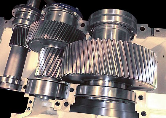
A refinement of the spur gear is the helical gear. Here the leading edges of the teeth are not parallel to the axis of rotation, but are set at angle. The gear is curved, with the tooth shape describing a segment of a helix. Helical gears can be meshed in parallel or crossed orientations (usually 90° i.e., skew gears) but the load capacity of crossed helical gears is much reduced.
Because the teeth are angled, they engage gradually. Each pair of teeth first make contact at a single point at one side of the gear wheel, and then a moving curve of contact grows gradually across the tooth face to a maximum, before receding until the teeth break contact at a single point. The result is far smoother and quieter operation than spur gearboxes. Due to the geometry and load directions on the gears, they are also able to handle higher torques than equivalent sized spur gears. Efficiency is similar, in the range of 94-98%.
A disadvantage of helical gears is the axial thrust inherent in the design. This requires appropriate thrust bearings to be incorporated, which impacts on lubrication requirements. This disadvantage must either be accommodated, or can be addressed by using gearboxes built around twin helical stages, with the helix angle of one being the negative of the other.
Another solution to the problem of radial thrust is the double helical (or herringbone) gear, in which two sets of helical teeth are set in a V shape with each cancelling out the axial thrust of the other. Like the helical gear, double helical gears transmit power smoothly. However, they are very expensive to manufacture, and really only suited to heavy machinery.
Bevel gears provide another option: gears where the two shafts intersect and the tooth-bearing faces of the gears themselves are shaped like cones. The design offers ultimate flexibility in the angle between the shafts, although 90° is most common. Considerations in specifying bevel gears are that the gears have to be precisely mounted, and the axes capable of supporting significant forces. Noise is also an issue at higher speeds.
Efficiencies are a little lower than the gear designs discussed so far, typically between 93 and 97%. However, they do handle lower gear ratios with high efficiency – better than helical gear designs. These gears are generally only used at lower speeds.
A variation on the bevel gear is the spiral bevel design, which offers similar advantages to helical gears in that the teeth engage more gradually, delivering smoother, quieter transmission. They also have very high efficiency, in the range 95-98%.
A further variation is the hypoid gear, which resembles spiral bevel gears except that the shaft axes do no interest. Hypoid gears are almost always designed to operate with the shafts at 90 degrees. They are stronger and quieter than spiral bevel gears, and offer high gear ratios in a single stage. However, mechanical efficiency is reduced, typically 80-85%. Also, these gears are paired and matched for life.
Worm gears sets include the worm itself which is meshed with an ordinary looking gear wheel. They provide a simple and compact way to achieve a high torque, low speed gear ratio. However the downside is considerably lower efficiency, which can be as low as 50%.
The planetary gearbox consists of one or more outer gears (planets) revolving around a central (sun) gear. A large outer ring gear (annulus) meshes with all the planets. The axes of all gears are parallel, so input and output shaft will always be inline. Planetary gearboxes are highly efficient (96-98% per stage of reduction) even at low speeds. They offer high gear ratios per stage, and are highly compact, able to transmit three times the torque of a similarly sized, conventional spur gearbox, because the load being transmitted is shared across multiple planets. Multi-stage planetary gearboxes can deliver extremely high ratios, and efficiencies losses are as little as 2% per stage.
Planetary gearboxes can also be combined with bevel and or helical gears to offer the best of both worlds in terms of performance characteristics, while also allowing the input and output shafts to be turned through 90 degrees. An example of such a hybrid design can be found in Brevini’s Posiplan gearbox. The Posiplan range uses a combination of planetary and helical gear technology to achieve an extremely compact and efficient solution in many applications.
It is worth noting that, regardless of the gearbox technology chosen, efficiency is affected among other things by the load, operating speed, the reduction ratio, the number of stages, ambient conditions and lubricant selection. For optimum efficiency, the gearbox should be carefully matched to load requirements. Optimum gearbox efficiency is obtained at maximum load, but efficiency decreases dramatically at light loads.
Other areas impacting on gearbox selection include mounting arrangements. Does the gearbox need to be flange mounted, or shaft mounted, or foot mounted. Not every technology will offer every option. And what about the materials of construction, which will impact on factors such as weight, transmission capabilities and longevity in operation. Numerous alloys, cast irons and even plastics are used in the manufacture of gears to give different performance characteristics and advantages. Steels are the most commonly used because of their high strength to weight ratio, but where weight is a prime concern a properly designed plastic gear can replace steel in particular applications, offering higher resistance to dirt and better low speed meshing.
As has been shown, there are many factors to consider when choosing the best gearbox technology and the decision making process is not always clear cut. At Brevini we always send out an expert sales engineer to asses each unique application and offer advice and design assistance where required. We can then advise and specify the correct gearbox for any task; meeting all the specific requirements for performance, size, mounting arrangements, reliability and longevity.


